How to setup the VPC on Cisco Nexus 9300 series switches step by step
How to setup the VPC on Cisco Nexus 9300 series switches step by step
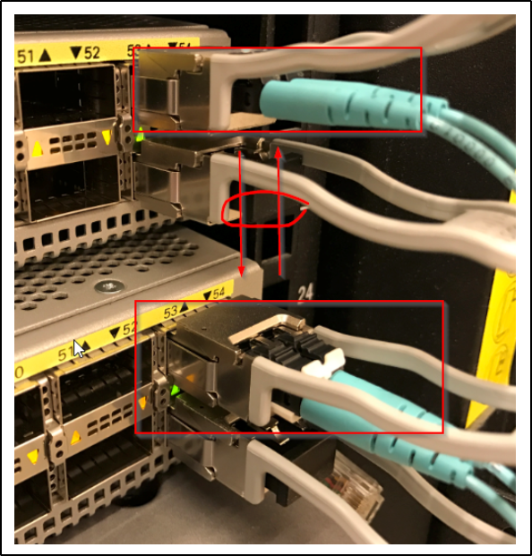
In this article, we will guide you through the step-by-step process of setting up Cisco Nexus switches. Begin by powering up the switches and connecting them using the TE ports. The following image illustrates the physical connections and cabling required for this setup.
Before proceeding, there are a few important factors you should verify and check, such as licenses and features.
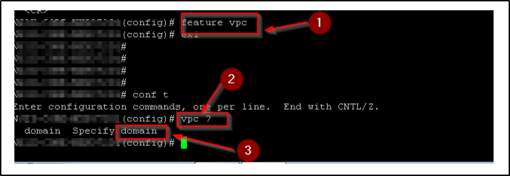
By default, certain features may not be enabled, so you need to enable the “VPC” (Virtual Port Channel) and “LACP” (Link Aggregation Control Protocol) features.
The provided screenshot illustrates the command to enable the VPC feature.
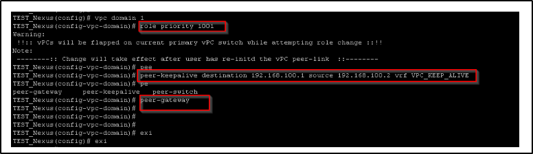
Now you will need to setup the VPC domain and the related configuration
- Setup the domain
- Setup the Role for the switch
- Setup the peer keepalive configurations where you will need IP addresses here – can use the /30 addresses
- Setup the peer-gateway
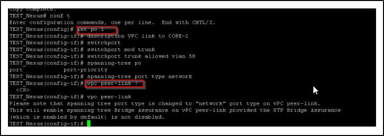
To set up the VPC Peer-Link port-channel, follow these configuration steps in the command-line interface:
- Enter configuration mode:
configure terminal
.
- Specify the interface as port-channel 1:
interface port-channel 1
.
- Add a description for the port-channel:
description [description]
.
- Configure the interface as a switchport:
switchport
.
- Set the switchport mode to trunk:
switchport mode trunk
.
- Allow the desired VLANs on the port-channel:
switchport trunk allowed vlan [VLAN IDs]
.
- Change the port type to “Network”:
spanning-tree port type network
.
- Enable the VPC peer-link on the port-channel:
vpc peer-link
.
By following these steps, you will successfully set up the VPC Peer-Link port-channel configuration.
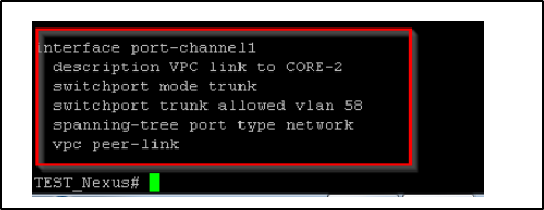
Below is the output of ” sh run int po 1″
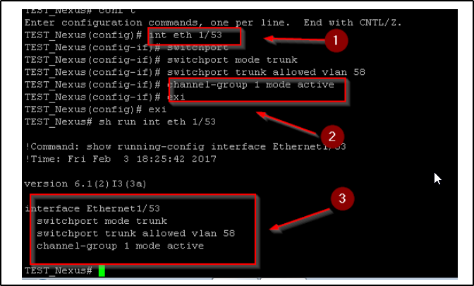
Now configure the physical interface where you have the Fiber cables connected – in this case, Port 1/53 is being used to carry the VPC peer-link” traffic
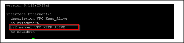
You will also need to configure the port for VPC keepalive- you can use any port for this, since this is only used for keepalive traffic – in this case Eth 1/1 is used
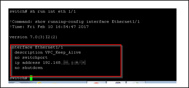
Make that interface part of the VRF group and assign the IP address from the previous config
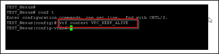
Add the VRF context in the global config mode
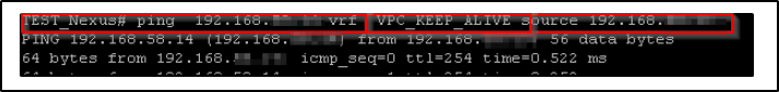
By this stage, you should be capable of performing VRF pings between devices, and Port Channel 1 should be active and visible. This indicates that you are now prepared to configure VPC Peer connections for your servers.
Here’s an example of how to conduct a VRF ping to verify connectivity:
Ensure that you replace
with the appropriate VRF name you wish to test, and
with the IP address of the intended destination device. Executing this command will help confirm the connectivity status between the VRFs.
Once you have successfully performed the VRF ping and established connectivity, you can proceed with the VPC Peer configurations for your servers.
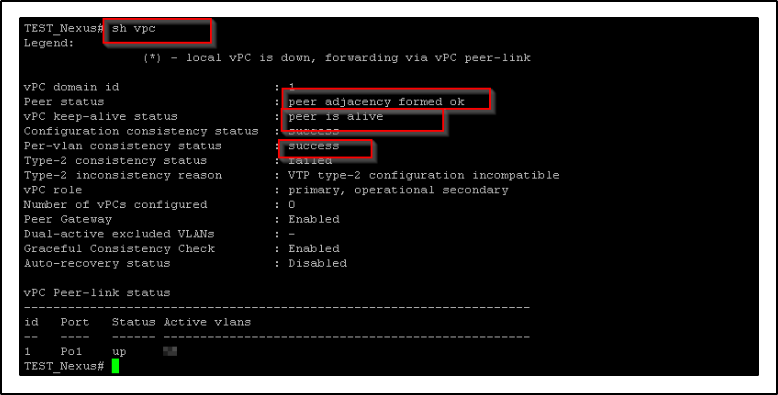
To verify the VPC (Virtual Port Channel) details and confirm the status of the peer, you can use the following command: “show vpc”.
Executing the “show vpc” command will display the relevant VPC information, including the status of the peer. Ensure that the output indicates that the peer is active and operational. This verification step ensures that the VPC setup is functioning as expected.